[{"id":95400886343,"handle":"all-products","title":"All Products","updated_at":"2023-09-30T01:45:04-04:00","body_html":"","published_at":"2019-08-30T20:14:20-04:00","sort_order":"alpha-asc","template_suffix":"","disjunctive":false,"rules":[{"column":"type","relation":"not_equals","condition":"Gift Card"}],"published_scope":"web","image":{"created_at":"2019-08-30T20:17:26-04:00","alt":null,"width":500,"height":500,"src":"\/\/www.filastruder.com\/cdn\/shop\/collections\/Homepage_All_Products.png?v=1606244748"}},{"id":2842689551,"handle":"duet3d","title":"Duet3D","updated_at":"2023-09-29T22:30:09-04:00","body_html":"","published_at":"2017-10-29T12:41:33-04:00","sort_order":"best-selling","template_suffix":"","disjunctive":true,"rules":[{"column":"vendor","relation":"equals","condition":"Think3DPrint3D"},{"column":"vendor","relation":"equals","condition":"Escher3D"}],"published_scope":"web"},{"id":169835268,"handle":"electronics","updated_at":"2023-09-30T01:45:04-04:00","published_at":"2016-01-30T13:35:00-05:00","sort_order":"manual","template_suffix":"","published_scope":"web","title":"Electronics","body_html":"Various electronics for use with your 3D printer.","image":{"created_at":"2018-12-01T12:15:38-05:00","alt":null,"width":500,"height":500,"src":"\/\/www.filastruder.com\/cdn\/shop\/collections\/3.png?v=1567183448"}},{"id":265815392327,"handle":"non-obx","title":"Non-ObX","updated_at":"2023-09-30T01:45:04-04:00","body_html":"","published_at":"2023-04-14T15:13:50-04:00","sort_order":"created-desc","template_suffix":"","disjunctive":false,"rules":[{"column":"title","relation":"not_equals","condition":"E3D Revo ObXidian Nozzle"}],"published_scope":"web"}]
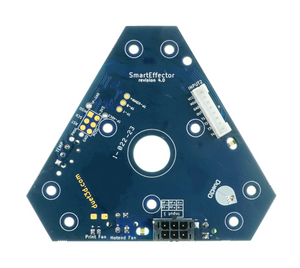
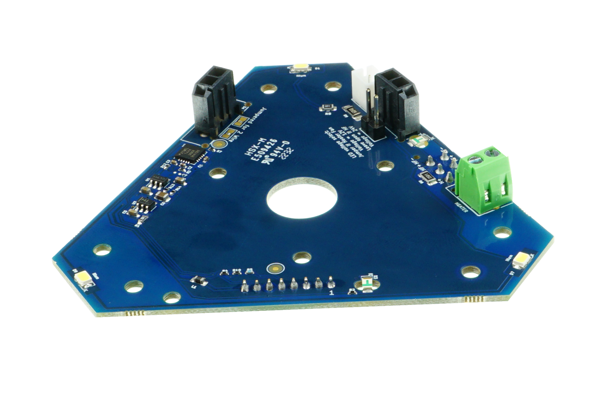
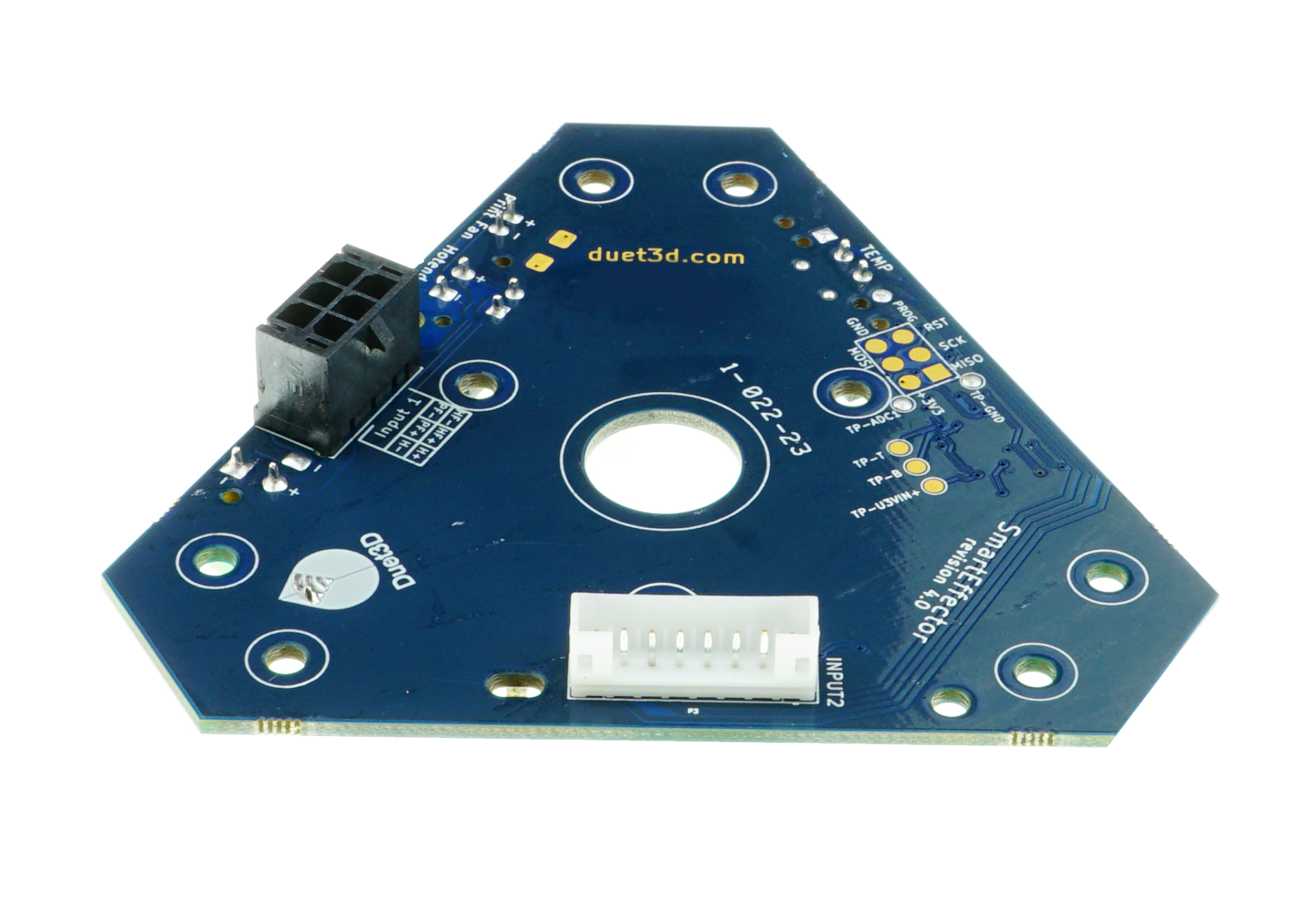
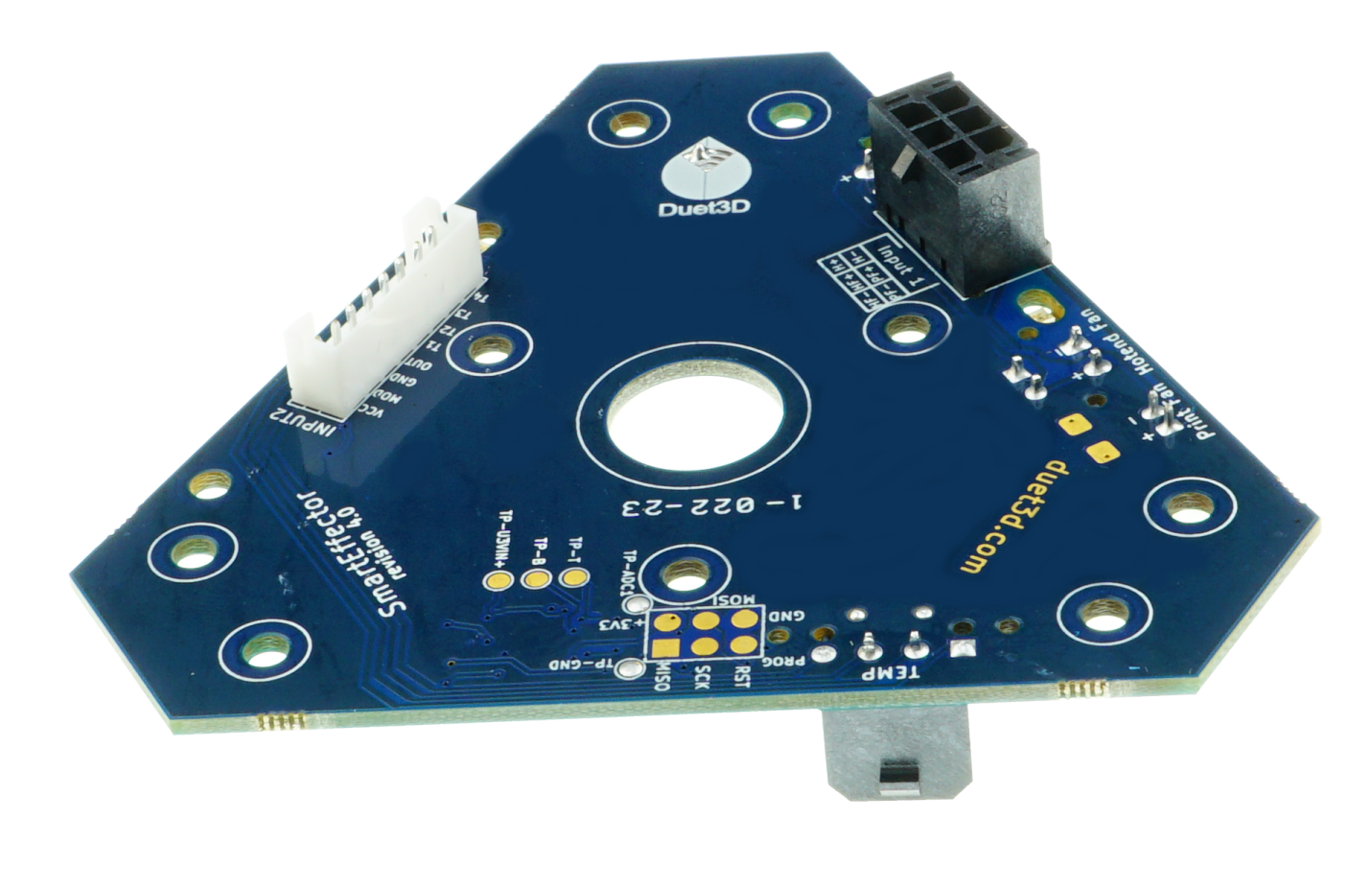
Uses built in traces in a custom PCB manufacturing process. Significantly finer straces allow for a higher noise margin.
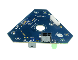
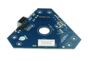
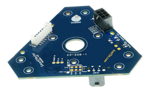
Changed the 8 pin connector on the top of the board to a JST PH which is more robust. The Molex KK 2 pin header on the bottom has also been changed to JST PH
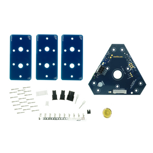
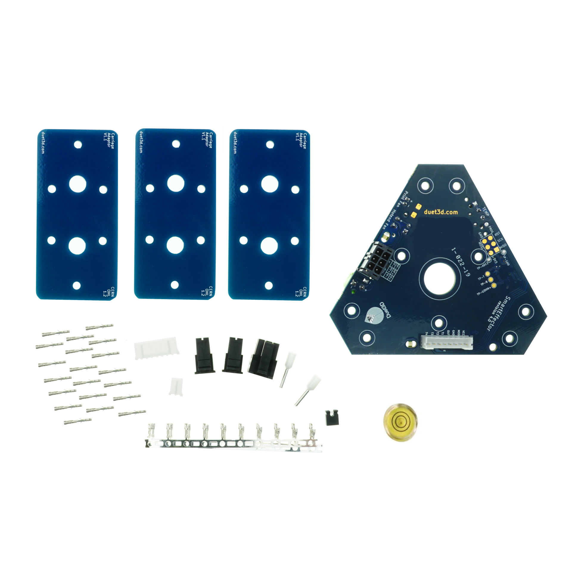
The Smart Effector for delta printers allows the hotend to be used as a Z probe giving fantastic accuracy across the whole delta build area by eliminating the effect of tilt. It uses precision PCB manufacturing to ensure equal hole spacing between the effector and the carriages on the towers, further improving accuracy.
Supplied with 3 PCB carriage adapters with 20mm mounting hole spacing compatible with common linear rails and wheel carriages.
We have various arm lengths available as an optional add on, including 215mm, 288mm, 304mm, 360mm, and 400mm. Click here for those.
We also list spare mag balls if you want to have multiple smart effectors for a quick swap.
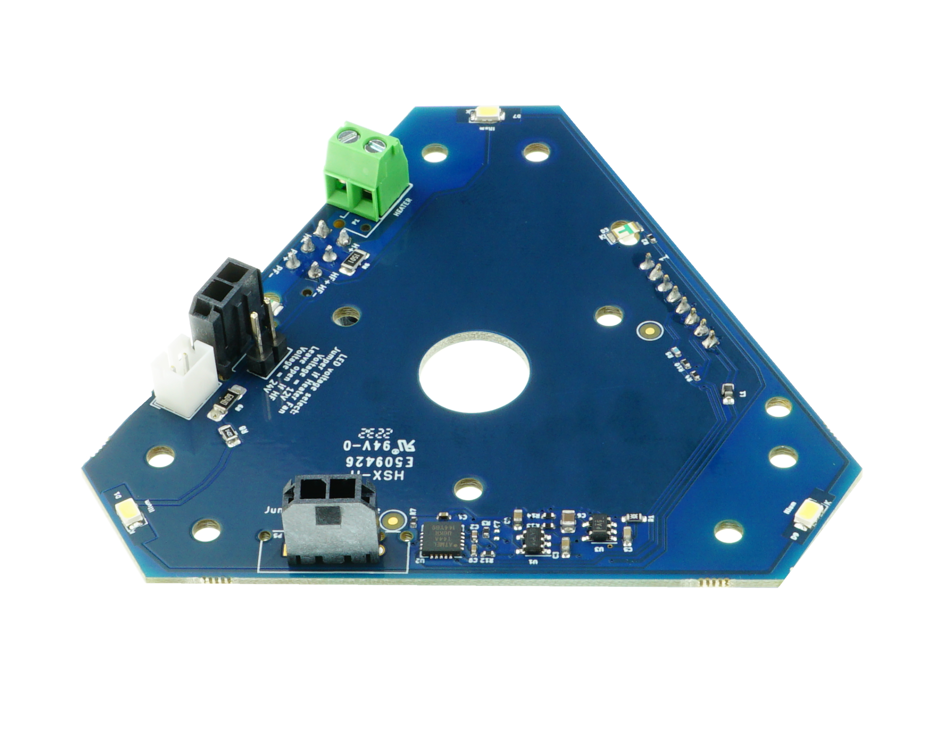
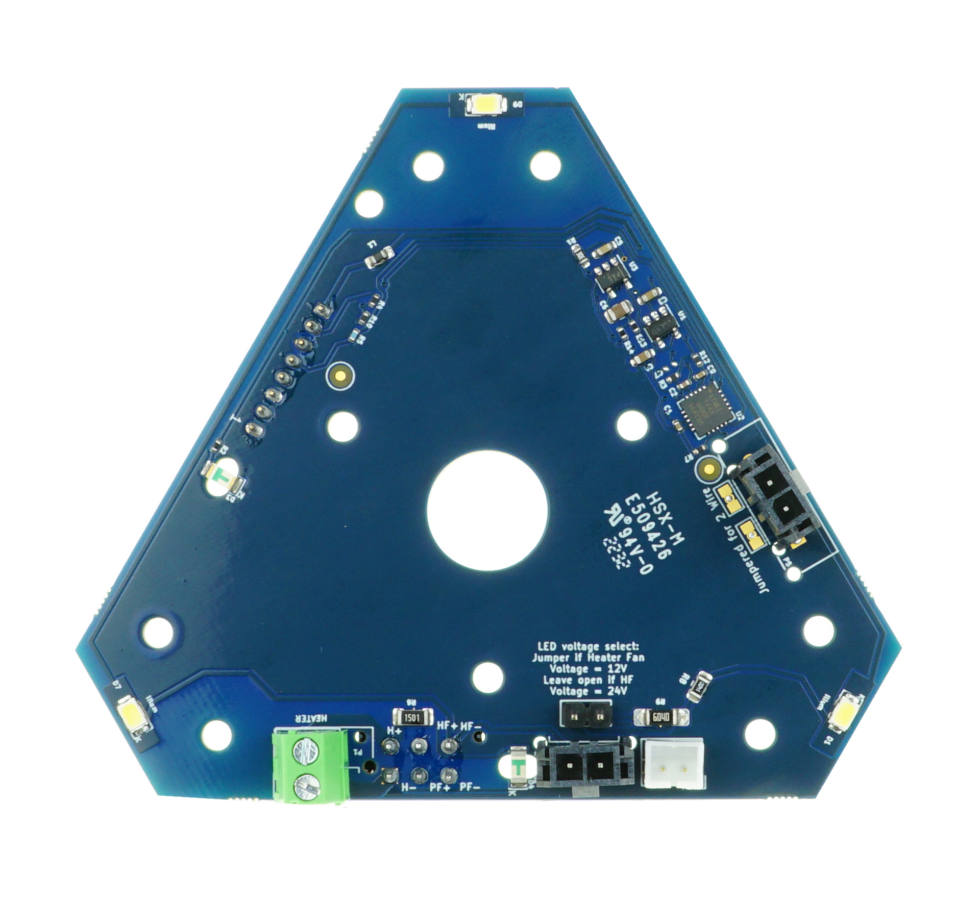
The smart effector simplifies wiring of hotend components with plug connectors from thermistor and fans along with a screw terminal for the heater cartridge. Molex and microfit connections are then used for wiring looms back to the control electronics. Crimp pins and housings are supplied for all connections
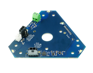
On board LEDs for print illumination are compatible with either 12V or 24V power supplies with a jumper selecting the voltage.
Three white LEDs to illuminate the bed whenever the hot end fan is powered
Green LED to indicate Z probe triggering and successful programming
Amber LED to indicate power to hot end heater
Matching PCB carriage adaptors ensure uniform spacing between bearings at top and bottom of the rods, for accurate nozzle motion
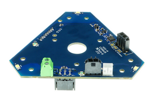
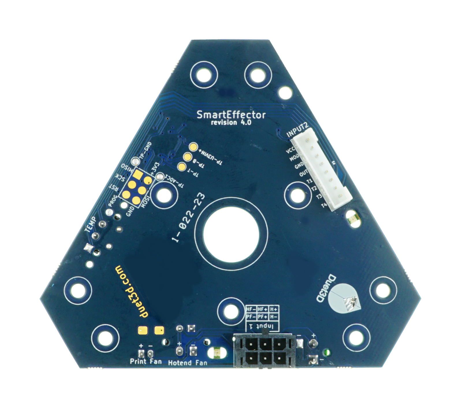
Power and signal connectors on top for connection to the 3D printer control electronics, to make removal of the hot end easier
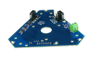
Connectors on underside for hot end heater, hot end fan, print cooling fan and temperature sensor
Support for thermistor, or 2-wire PT100 temperature sensor with 2- or 4-wire connection back to electronics (version for 4-wire PT100 sensor available to special order)
Effector and carriage adapters suit magnetic ball studs with M3 tails
carriage adapters suit carriages with 4 x M3 fixing holes in a 20mm square
Compatible with 12V and 24V heaters, and 12V and 24V hot end fan power (jumper selectable)
3.3V or 5V supply needed for nozzle contact sensor
Programmable nozzle contact sensitivity when used with Duet series electronics
Dimensions
Strain Effector Dimensions
Carriage Adaptor Dimensions
SmartEffector SMT Component Clearances
For those people who want to make parts that fit flush with the underside of the board this gives the approximate clearances for SMT components on the bottom of the board.
Parts supplied (this is all that's included)
Qty
Item
Remarks
1
Assembled and tested PCB effector
3
PCB carriage adapter
2
6- way Molex Microfit 3 shell (black)
2
2-way Molex Microfit 3 shell (black)
1
8-way Molex KK shell (white)
1
2-way Molex KK shell (white)
16
Crimp pins for Microfit shells
12
Crimp pins for KK shells
2
Small ferrules for terminating heater wires
not needed if your effector uses a 2-pin Microfit connector for the heater instead of a terminal block - They are supplied with a terminal block by default
1
M12 half nut
1
M12 plastic or fibre washer
1
18mm or 20mm round spirit level
Optional add ons (click bold text below for links)
Small flat-blade screwdriver, if your effector has a terminal block for the heater connection
Connectors and Wiring
Top side
The power connector (Input 1) is a 2 x 3 pin black Molex Microfit 3 connector. The pins are labelled on the underside and should be connected as follows:
Label
Pin function
Connect to where on Duet
H+
Heater positive
E0 HEAT terminal block, VIN pin
H-
Heater negative
E0 HEAT terminal block, E0- pin
HF+
Hot end heatsink fan positive
V_FAN pin on your chosen hot end fan output (typically FAN1)
PF+
Print cooling fan positive
V_FAN pin on your chosen print fan output (typically FAN0)
HF-
Hot end heatsink fan negative
FAN- pin on your chosen hot end fan output (typically FAN1)
PF-
Print cooling fan negative
FAN- pin on your chosen print fan output (typically FAN0)
The HF+ and HF- pins also power the illumination LEDs.
The signal connector (Input 2) is an 8-way white Molex KK connector. The pins are labelled on the underside and should be connected as follows:
Label
Pin function
Connect to where on Duet
1
PT100 current feed
If using a 4-wire PT100 connection, connect to pin 1 of the terminal block on the PT100 daughter board. Otherwise leave unconnected.
2
PT100 voltage sense, or thermistor
Pin 2 of PT100 terminal block if using a PT100, or E0_TEMP if using a thermistor
3
PT100 voltage sense, or thermistor
Pin 3 of PT100 terminal block if using a PT100, or E0_TEMP (other pin) if using a thermistor
4
PT100 current feed
If using a 4-wire PT100 connection, connect to pin 4 of the terminal block on the PT100 daughter board. Otherwise leave unconnected.
5
Output from nozzle contact sensor
Z-probe connector IN pin
6
Ground
Z-probe connector GND pin
7
Control input
Z-probe connector MOD pin
8
3.3V or 5V power
Z-probe connector 3.3V pin
The 4 connections for the Z probe are in the same order as the Z probe connector on the Duet. Similarly for the PT100 connections.
Underside
Label
Connector type
Connect to what
TEMP
2- or 4-pin black Microfit 3
Thermistor or PT100 sensor
HEATER
2-way terminal block or 2-pin black Microfit 3
Hot end heater cartridge
Hotend fan
2-pin white Microfit 3 (Molex KK on prototypes)
E3D heatsink fan (red to +, black to -)
Print fan
2-pin white Molex KK
Print cooling fan.Important!On theprototypes onlythe + and - labels are swapped, so you need to connect red to - and, black to +.
on for 12V
2-pin header
Place a jumper over this if using 12V hot end fan power. Leave off for 24V.
Heatsink thermistor (prototypes only)
2-pin black Microfit 3
Leave unconnected
P2
2x3 pads
Do not connect (these are used to program the microcontroller)
You can use a 4-wire PT100 connection from the effector back to the Duet even if you are using a 2-pin PT100 sensor with a 2-pin connector.
Warnings
The heatsink must be accurately centred in the effector. Production versions of the E3D heatsink have a shoulder to make it self-centering. If you have a prototype heatsink, use either the plastic split washer or the spacer, so that the PCB traces on the underside are clear of the heatsink.
Take care not to damage the fine traces on the PCB during assembly!
Once you have inserted the crimp pins into the black Molex shells, they are impossible to remove without an expensive tool. So make quite sure that the crimp connection is secure, and make sure you have it in the correct hole before pushing it home. We supply 1 spare 6-way shell and some spare crimp pins.
If you have a prototype effector, one of the rods may foul the corner of the 8-way white Molex connector when the nozzle is at the extreme edge of the bed. Please check for this, and if necessary restrict the probing radius and printing radius to avoid this, and/or file down the corner of the connector shell.
Assembly
Effector and hot end
Attach the ball studs to the effector using M3 washers and nuts (you can use plain or nylock nuts, your choice). The balls must be on the top side, which is the side with the 6-way and 8-way connectors. If you will be using our print cooling fan duct design, leave off the two ball studs in the corner adjacent to the "Duet3D Compatible" logo and text because the fan mount will also be attached there. Tighten with 10mm and 5.5mm spanners.Position the 5.5mm spanner on the nut carefully, to avoid damaging the surface-mount LEDs on the underside of the board adjacent to the nuts.
If you will be using a 12V supply for the hot end fan, fit the jumper supplied across the pins labelled "on for 12V". Leave the jumper off for 24V.
If the thermistor or PT100 sensor does not already have a short cable terminating in a black 2-pin Molex Microfit plug, cut the cable to 60mm to 80mm length and fit the plug.
If your hot end fan does not already have a short cable terminating in a black 2-pin Molex Microfit plug, cut the cable to 60mm to 80mm length and fit the plug.
Assemble the E3D hot end, or replace the heatsink on your existing one. Don't forget to put a collet in the top of the heatsink if it doesn't already have one fitted. Note that the fan assembly must be fitted with the overhang at the bottom, unless you use a 4mm spacer between the heatsink and the effector (see later).
If using a prototype heatsink, temporarily place the printed split washer over the top of the heatsink above the threaded section and make sure that the hole in the top of the effector can just fit around the washer. If necessary, trim the washer with a knife. Then screw the split washer all the way down the threaded part of the top of the heatsink until it it over the smooth section below the thread. If you use a printer spacer between the heatsink and the effector (see later) then you do not need the split washer.
Put the top of the heatsink through the hole in the bottom of the effector, all the way until the effector is against the the top heatsink fin (which is smaller than the other heatsink fins). Make sure that the heatsink is centred in the effector.
Put the fibre or plastic washer above the PCB over the heatsink thread, then secure the effector to the heatsink using the nut. Do not tighten it yet.
If you are using our print cooling fan design, rotate the hot end so that the protruding end of the heater block faces towards the edge of the effector that carries the two white 2-pin Molex KK connectors (see photo later). This is to leave room for the print cooling fan, which will be attached to the opposite corner.
Tighten the nut. You can use a strap wrench to hold the heatsink body in place if necessary.
If your PCB effector has a 2-pin terminal block for the heater leads (labelled H on the top side), trim the cartridge heater leads to the required length, strip the ends, and crimp the ferrules on. Then attach the wires to the screw terminals. If your PCB effector has a third black 2-pin Molex Microfit connector for the heater connection instead, this is for the new version of the E3D cartridge heater that has a Molex Microfit plug attached already, and you can just plug it in.
Plug the thermistor or PT100 sensor into the 2-pin socket labelled TEMP.
Plug the hot end fan into the socket labelled Hotend Fan.
You can optionally print a spacer, 16mm outside diameter x 12mm inside diameter x about 4mm long to fit between the heatsink and the effector, to allow more room below the effector.
At this stage your effector should look like this, viewed from the underside.
Print cooling fan assembly
Push the brass inserts into the fan duct, using a warm soldering iron to help them if necessary
Cut the fan wires to length and terminate them in a 2-pin Molex KK shell, observing correct polarity (see photo)
Put the side of the fan with the label on it against the fan duct, rotated so that the wires are in an appropriate position, and secure it using two M3x10mm screws into the brass inserts
Place the fan bracket over the other two holes on the front of the fan, then secure it using two M3x20mm screws and Nylock nuts
Your print cooling fan assembly should look like this. The fan duct was printed green and the fan bracket was printed red.
Effector final assembly
Secure the fan bracket to the underside of the effector using the two remaining ball studs and M3 nuts. Make sure that the fan duct is not right up against the hot end heater block.
If desired, secure the round spirit level to the top surface with superglue or double sided adhesive tape.
Here are some images showing the placement of the print cooling fan. The fan duct was printed green and the fan bracket was printed red.
Carriage adapters
Fit 2 ball studs to the outer holes in each carriage adaptor. Then fit the carriage adapters between your carriages and the linear sliders or wheeled trucks.
Commissioning
The following instructions assume you are using the effector with Duet electronics.
Double-check that you have made the right connections
In your config.g file select Z probe type 5, feed rate 1000 and recovery time 0.4 seconds in your M558 command (M558 P5 R0.4 F1000 + whatever other parameters you want)
In your config.g file select probe threshold 100, trigger height -0.1, and zero XY offsets in your G31 command (G31 P100 X0 Y0 Z-0.1)
Power up your printer electronics using 5V or USB power only. Three seconds after power up, the green LED should flash twice.
Give the hot end nozzle a gentle but sharp tap upwards (if the nozzle is cold, you can use your finger for this). The green LED should flash each time you tap it, indicating that the nozzle contact sensor has triggered and a pulse has been sent to the electronics.
Apply 12V or 24V power to your electronics. If your hot end fan is wired permanently to 12V or 24V then the three illumination LEDs should light up and the hot end fan should run. If you are using thermostatic control of the hot end fan, command your hot end to a temperature just high enough for the thermostatic fan control you are using to kick in, and make sure that the fan and illumination turn on when the threshold temperature is reached.
Home the printer, then send command G30 to start a single probing move. Tap the nozzle upwards; the green LED should flash and the probing move should stop.
If that is working, home the printer again and run auto calibration. Caution: your effector to nozzle distance will probably be different from whatever it was before you installed the PCB effector. So measure the homed height again and put that figure into the H parameter in your M665 command. Also set the M558 H parameter to a larger value temporarily (e.g. 30) to start probing from a greater height, until you have completed calibration.
Programming the sensitivity
The force needed to trigger the sensor is programmable on a scale of 0 to 255. The default is 50. You can adjust the sensitivity according to your needs:
Lower numbers need less nozzle contact force to trigger the sensor. However, there is a greater risk that vibration from the stepper motors will cause false triggering. Also, electrical or magnetic interference from the heatsink fan and/or hot end fan may cause false triggering. [False triggering when the effector is moving between probe points doesn't matter if you use the recommended 0.4 seconds recovery time.]
Higher numbers make the sensor more resistant to false triggering, at the expense of needing a greater nozzle contact force.
To program the sensor, send commandM672 S105:aaa:bbbreplacingaaaby the desired sensitivity andbbbby 255 -aaa. The green LED will flash 4 times if the command is accepted. When you subsequently power up the effector, the green LED will flash three times instead of twice to indicate that a custom sensitivity is being used.
To revert to factory settings, send commandM672 S131:131. The green LED will flash 5 times if the command is accepted. When you subsequently power up the effector, the green LED will flash twice to indicate that default settings are being used.